 Flowtera Pipe
Mechanical Strength
A 415 MPa minimum tensile-strength level is commonly associated with carbon-steel pipe grades such as ASTM A53 Grade B and API 5L Grade B.
Pipe failures rarely begin with a dramatic rupture. They often start as a thin wall, a hidden weld flaw, or a small dent near a support. That is why engineers must ask how to test pipe strength and quality before installation and during service. In 2026, reliable inspection combines established standards with better data, imaging, and risk-based decisions.
J. Phillip Ellenberger, a recognized piping engineer and author, states, “A piping system is only as reliable as its weakest component.” This practical warning still matters. A strong-looking pipe can contain porosity, incorrect alloy, poor heat treatment, or dimensional damage. Visual inspection provides the first clue. Hydrostatic testing checks pressure resistance. Ultrasonic thickness measurement reveals metal loss. Radiography or phased-array ultrasonic testing can examine critical welds. Positive material identification confirms the alloy.
No single method catches everything. That is easy to forget.
A dependable program should compare test results with ASTM, ASME, ISO, and project requirements. Inspectors should record pressure, holding time, temperature, calibration status, and exact test locations. For example, a pressure drop beside a welded elbow deserves closer attention than a clean reading on a straight section. Experienced teams also review manufacturing records and service history, not only final test certificates. Some assumptions may fail in the field. Therefore, this guide examines the best ways to test pipe strength and quality in 2026, while recognizing that safe decisions require qualified personnel, traceable evidence, and thoughtful review.
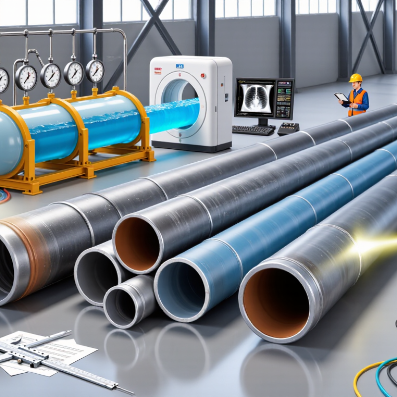
Before testing pipe strength, define what “strong enough” means for the service. Record the fluid, operating pressure, temperature, pipe diameter, wall thickness, and expected service life. Include pressure surges, external loads, vibration, and corrosion allowance. A pipe carrying hot water needs different requirements from one exposed to chemicals or buried soil.
Set measurable acceptance limits. Specify minimum yield strength, tensile strength, allowable pressure, wall-thickness tolerance, weld quality, and dimensional accuracy. Select recognized testing methods that match the pipe material and design code. Common checks include hydrostatic pressure testing, tensile testing, hardness measurement, and ultrasonic examination. Visual inspection still matters. Small surface cracks can become serious failures.
Ask for material certificates, heat numbers, manufacturing records, and calibration details for test equipment. Inspectors should compare samples with the written specification, not personal assumptions. In field work, I have seen a pipe pass a pressure test but show unacceptable wall loss near a joint. That result required further investigation, not a quick approval. Test conditions also need careful control, including water temperature, pressure-holding time, and instrument accuracy. No single test proves every quality requirement. Sampling plans can miss local defects, and repeated testing may reveal inconsistent production. Define how failed samples are handled before testing begins.
Choose a representative sample from the correct heat, batch, and production stage. Record its identification, wall thickness, diameter, and cutting location. A small sample can mislead. Consider extra samples after welding, forming, heat treatment, or visible damage.
Remove burrs, scale, oil, and moisture carefully. Do not change the original surface condition. Clean surfaces support more reliable readings. Rushed preparation remains a common weakness.
Verify load cells, pressure gauges, extensometers, and ultrasonic probes. Use calibrated gauges to confirm specimen dimensions. Calibration records should include traceability and expiry dates. These details are easy to overlook.
Measure tensile strength, yield strength, elongation, and hardness when required. Pull the cut specimen until it deforms or breaks. Record its location, dimensions, temperature, and test equipment condition. Unusual fractures deserve experienced review.
Fill the pipe with a suitable test medium. Remove trapped air before increasing pressure. Raise pressure gradually and hold the target level for the required period. Watch the gauge continuously. Small changes matter.
Inspect joints, welds, fittings, and connections carefully. A pressure drop may indicate expansion, a loose fitting, or a hidden leak. A gauge can look stable while a connection remains poorly tightened. That mistake deserves review.
Visual checks may reveal moisture around a joint. Sensitive methods can detect pressure loss or escaping gas. Clean surfaces help prevent false readings. Repeat testing after repairs, not merely after instrument adjustment.
Keep raw readings instead of recording only pass-or-fail outcomes. Include time-stamped records, photographs, test conditions, and corrective actions. Cite the current applicable standard in the final report. A passing result helps. Clear evidence matters more.
Testing pipe strength and quality begins by defining clear requirements for the pipe’s material, dimensions, intended service conditions, pressure rating, and applicable quality standards. A reliable process should include representative sample preparation, calibrated testing equipment, and documented procedures. The question of how to test pipe strength and quality should be answered through a combination of visual inspection, dimensional checks, and non-destructive methods that can identify cracks, corrosion, inclusions, weld imperfections, or wall-thickness variations without damaging the pipe.
Mechanical tests can then assess tensile strength, hardness, flexibility, and resistance to deformation, while hydrostatic or pneumatic pressure tests help confirm pressure performance and reveal leakage risks. Test results should be recorded accurately, compared with predefined acceptance criteria, and reviewed for consistency. Any failed sample or unusual reading should trigger further investigation, additional testing, or corrective action. Final quality verification should confirm that the pipe meets its design requirements, safety expectations, and relevant industry standards before it is approved for use.
